


Making An Automatic Load Sensing Switch Fun & Interesting
This is another project that I’ve been meaning to make for a while, and with my change to localized dust collection, I figured now was as good a time as any.
First, a word of warning: this project deals with mains voltage, and if you have any doubts or concerns about working with it, this project may not be for you. There is a serious risk of shock, fire and possibly death unless all safety precautions are followed. Do not attempt construction of this project unless you are completely confident in your ability to work with mains voltage safely.
I made a video showing the device and going over briefly how it works before making a simple case for it using PVC pipe:

The completed project is fairly compact:
.jpg)
I’ll now go into some detail on how the circuit works. Basically, it detects a voltage drop across a large bridge rectifier that acts as a high power shunt that is wired in series with the line that goes from the outlet to the tool that will be used to trigger it. It is very important that the hot wire (typically black), and not the neutral (typically white) is used.
The small voltage that drops across the bridge rectifier in then stepped up using a transformer with its secondary connected to the bridge. The transformer must be a fairly low voltage secondary, I’m using 6vac from an old clock radio. The primary is 120vac and the amperage of the transformer must be high enough to develop enough current to drive the relay that powers the vacuum.
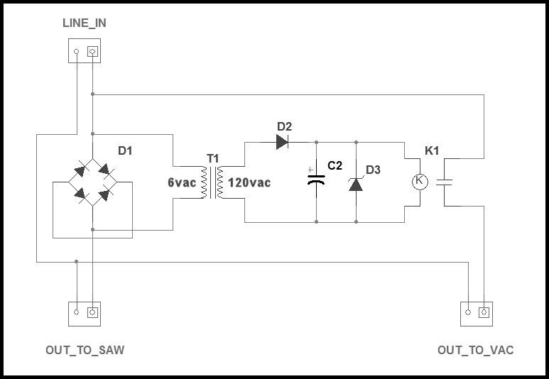
The circuit diagram shows how it will be wired and here are the parts used:
D1 is a 35 amp, 600 volt bridge rectifier
T1 is a small transformer (details in the text above)
D2 is a diode 1N4001 or similar to change the AC voltage from T1 to DC
C2 is an electrolytic capacitor 100uF, 50V
D3 is a 10 volt zener diode keeps the voltage at or below 10vdc
K1 is a relay with a 12vdc coil. Mine has a coil resistance of 380 ohms.
These are the parts that I used for the one I made. Some adjustment will be required if you are using a different size transformer and relay.
Another possibility is to use a solid state relay (SSR) instead of a mechanical one. SSRs require less current and voltage to trigger and will work with a smaller (amperage wise) transformer. SSRs are generally more expensive than mechanical ones, and I didn’t have any on hand while making this project.
The bridge rectifier must be rated high enough for a wide safety margin. I used one rated for 35 amps and these are fairly inexpensive. The “+” and “-” on the bridge are wired together, while the two “~” terminals are wired in series with the load
The bridge rectifier will get warm while the saw is running, so I attached it to a small piece of aluminum to act as a heatsink. Normal intermittent use will never get the bridge any hotter than warm, but if it is going to be used for extended periods, some small holes should be drilled through the case to provide ventilation. These holes must be small enough so that fingers can’t reach anything inside the case.


I tried using several transformers and had the best results with one that is rated for a 6vac, .5 amp secondary. If you use a larger transformer, it will have to deliver more amperage as well. There will be some trial and error unless you are using the exact same parts as I used for mine.
My relay is a small 12 amp (switch) that is normally open (NO). When the coil is energized, it will close the switch and start the vacuum:
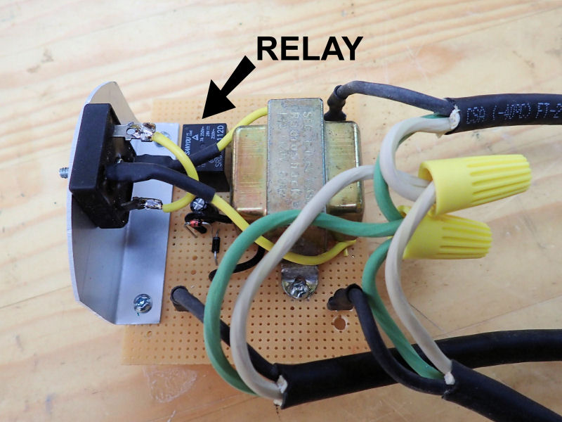

I decided to wire everything on a piece of perf board, but this can be made using a point to point method. Care MUST be taken that all of the wires are routed correctly and any bare conductor on the perf board that is at mains potential be well away from other conductors. I used quick connect terminals on my board, but that was just for convenience during testing. It would be better to connect the wires directly.
The lead in wires must be large enough to carry the combined current of the saw and the vacuum. I used 14 gauge wire and kept the leads short.
For the case I used 4″ PVC pipe and regular end caps. The wires that lead into the case are three conductor and the grounds from all three are securely tired together inside the case. If you make the case from metal, that will have to be connected to the ground wire. Any exposed metal (even screws) that go through to the interior of the case will need to be grounded
I made simple strain relief clamps from strips of PVC and bolted those onto the wires to prevent them from being pulled out:
.jpg)
.jpg)
The ground and neutral wires are connected with wire nuts and then wrapped with electrical tape to keep the wire nuts from coming loose..
I put some heavy dabs of hot melt glue to hold the board in place inside the case:
.jpg)
To close the case, I used regular end caps and screws that are short enough so that they don’t protrude inside the case. The caps can be glued, but that would make it nearly impossible to open, if something needs service.


