Making A Wooden Table Saw Homemade Machines & Jigs
Yes! Another one
This one is a bit different in that it will be a “real” table saw that uses a real table saw arbor. The material I’ll be making it from is mostly 1/2″ Baltic birch plywood, with some 3/4″ and some solid wood mixed in. I also have a sheet of 1/2″ plastic that will be used for the trunnions and top.
Like with my still unfinished Epic table saw, the best place to start is right at the heart of the saw, where the arbor is. I made these two identical parts from 1/2″ Baltic birch plywood that make up the blade lift part of the saw:

The smaller hole is the pivot point and the slot for the lift mechanism.
The larger holes are for the arbor bearings and I added backer pieces with slightly smaller holes for the bearings to seat against:

With the arbor installed and that much assembled, you can start to see how this will work:

I’m calling this part the truck (like on a skate board) and it moves back and forth while the bearings fit in the slots in the blade lift:

Moving back lowers the blade and forward raises the blade.

The lead screw is a 1/2″ threaded rod.
Now on to the blade tilt section, that starts with these two ends that have the trunnion radius laid out:

I used my compact compass to do that. The radius is 3″ and it’s important to mark it out accurately to precisely line up the trunnions later.
I left the parts long to lay out the radius, since it’s actually above the part:

The centre of that radius is in line with the edge of the blade at the table top surface.
I cut out two smaller pieces of plywood for the pivot block at the front, and cut a 5/8″ steel rod to use as the axle:

I did the same at the back of the tilt and fasten the end pieces:

With the lift adjusted all the way down, I saw a problem: I’m designing this as I go (and probably a bit too quickly), and I didn’t notice the angle the slot is at when fully down like this:
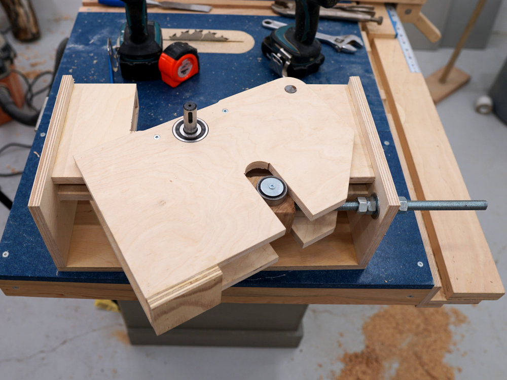
It may never be a problem, but it’s kind of sloppy and certainly not optimal, so I filled in the slot:

And recut it at a curve that will keep the bearing flat against the wall of the slot:

And here it is with the blade put on for a video thumbnail photo, and you can see how compact the assembly is:

And speaking of video, here’s the first. It covers the parts of the build up to this point:
I spent much of a full day cleaning the dust wax out of this motor (used in a table saw that was from a candle factory) and rewiring it to run in reverse:

This is the motor used on this table saw, and I didn’t realize at the time it was so fully packed with wax that it inhibited effective cooling. And while I was successful in reversing the motor, I later changed it back after giving it a bit more thought.
I also went back to the drawing board and refined the design a bit further and made some changes and additions. First was to widen the end pieces where the trunnions attach:

The yellow arrow points to the strip of plywood I added on both ends using glue and long screws. I added these to make is so that they could be connected to stiffen the assembly and keep it from twisting.
I added a bolt near the pivot point to squeeze the parts together and reduce play:

And drilled a small hole through the pivot pin on one end and used a finish nail to lock it in place:

And here’s how it looks now:

Notice the panel on the pulley side of the tilt that connects the front and back. This adds a massive amount of stiffness to the assembly and I feel a bit stupid for not realizing it during the initial design.
The tilt trunnions are made from that plastic I mentioned above, and are cut using my trim router with my homemade circle jig:

The part needs to be oversized to begin with for the pivot point, but will be cut to fit after:

I could have used plywood for both the trunnions and trunnion frames, but I had the plastic. Another good material would be a plastic cutting board the right thickness.
It’s critical that the trunnion fit perfectly in the trunnion frame, so having it there for direct comparison is a good idea:

Like the trunnions, these frames start out oversized for the pivot, then are cut down to final size after the bulk of the circle cutting is done. I left just a very thin layer at the bottom to hold it all together:

And here they are assembled and in place of the ends of the tilt:

Most saws only have two trunnions, but mine has a third. It’s much bigger (18″ radius) and is used to help support the motor:

The weight of the motor is a major problem for a saw build from wood like this, since it has to move with the lift and tilt. That third trunnion will take the weight of the motor off of the main trunnions and should reduce the amount of vibration as well, since it will be rigidly locked in place (with regard to tilt) when set at a cutting angle.
More because I wanted to demonstrate the lift action more dramatically in the video, I made the hand wheel for the lift:

It’s 8″ in diameter and made from 3/4″ plywood. The holes are there to make it look cool.
The handle is a solid piece of cherry (I think) that I have in my drill press to sand smooth:

Could have used the lathe to make this part, but I thought it would be interesting to use tools that are more common.
At my router table, I chamfered all of the holes and rim of the wheel:


Here it is set up temporarily to show the lift and tilt in action:
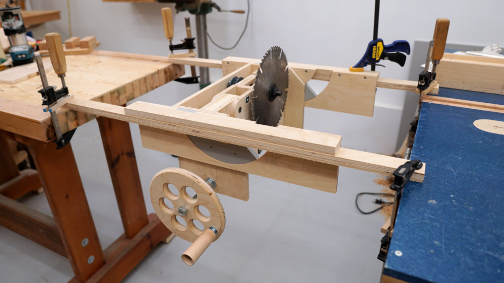

Very smooth, and you can watch that in this video:
Continue to part 2…
