How To Make A Sander Homemade Machines & Jigs
To get started on this sander project, I located a suitable motor. This is from a pedestal style sump pump (shown below) and these are very common. Often the pump itself wears out and gets discarded, but the motor still works just fine. Even new, these are often incredibly inexpensive, so getting one on sale is not out of the question.
The one I have is 1/3 hp and runs at 1725 rpm. Size and speed are important, since this sander really doesn’t need a very powerful motor, and will not be as effective for sanding wood with one that is faster.
The total length is 8-1/2″ (216mm), body diameter and body length is 5-3/4″ (146mm). The shaft is 1/2″ (12.7mm) and is 1-1/4″ (32mm) long. The part on the front of the motor that was fastened to the pedestal pipe is 1-7/8″ (48mm) diameter and 1″ (25mm) long. There is a round projection on the back cover that is 1-3/4″ (44mm) diameter and 3/8″ (10mm) long:

The shaft rotates counter-clockwise, when viewed from the front. That’s typical for these motors, but it’s best to confirm that before committing, since these are very difficult to reverse.
Wiring is something that doesn’t have to be complex. Here I’ve actually fastened a metal electrical box to the end cover for the power cord and switch:

I used small sheet metal screws to attach the box, and removed the end cover on the motor to do that. If your motor comes with a longer cord, it would make sense to mount the switch separately, rather than doing this. The wires on mine were extremely short and mounting the box on the motor was the best approach.
On to cutting out the parts, the sander is designed to be made from 1/2″ (13mm) plywood exclusively to simplify the build as much as possible. I used Baltic birch, but any good quality cabinet grade plywood will work. Although it is possible, I don’t recommend using MDF or particle board to build this.
Here I’m cutting out the main upright and doing a stop cut for the notch at the top:

I then finished the cut with my band saw, but a jigsaw or hand saw would work as well.
This part also has a notch at the top with angled sides (revised in the plan to one side angled) and I marked this out using the dimensions on the plan before cutting it out on the band saw:

This notch is for the upper wheel bracket assembly and allows that to move to adjust the tracking and tension of the belt.
The main upright has two t-nut locations and I’m drilling shallow counterbores with a 3/4″ (19mm) forstner bit:

Then drill through with a 5/16″ (8mm) bit:

There are five places where t-nuts are used in the same way, with a shallow counterbore drilled before the through hole.
The divider is the front mounting bracket for the motor, and needs a hole to match the nose on that. Mine is 1-7/8″ (48mm) and I drilled the closest size to that, then sanded the hole to fit:

If you have a motor that doesn’t have this nose extension, or has a mounting bracket already attached, you will have to devise another way to mount it. The main thing is that the shaft is in the right place and the motor is held firmly.
The lower disk cover has a circular cut-out that’s just slightly bigger than the lower wheel, and I’m using my compact compass to draw that arc:

I have a scrap of plywood the same thickness to extend the pivot point outside the part and the radius I’ve set the compass to matches the points marked on the part from the plans.
It also needs a hole for a snug fit on the shop vac hose used for dust collection :

If you think you will be doing a lot of angled sanding with the disk, it may be better to locate the dust collection hole in the front panel of the sander instead. As it is, the hose will get in the way when tilting the disk table. I very, very rarely change the disk table from 90 degrees, so having the hose here works best for me.
The wheels are made from three layers of plywood, and I cut the blanks square and slightly oversized. The pivot points for the upper wheels will be the bearings used for the upper wheel, and I drilled those after marking the centers:

This is a stepped hole, with the 7/8″ (22mm) one drilled to match the thickness of the bearing:

I’ll be using a router with a circle jig to cut these out, and used double sided tape to hole the blanks on scrap plywood to do that:

Here’s the circle jig – just a threaded rod screwed into the base of the router and a pivot block with shank of a 3/8″ drill bit put in. The bit fits the bearings used:

The cutting is done in three passes, going deeper with each one:


This method produces nearly perfect wheel blanks, since it’s pivoting on the bearing that will be used in the finished wheel.
The lower wheel blanks are made the same way, except instead of making a hole for the bearing, just a 3/8″ pivot hole is needed for the shank of the drill bit to fit into. Two of the lower blanks need to be cut out to clear the pulley, and I really should have drawn this circle before drilling the pivot hole:

I used the jigsaw to cut out the middle:

And then trued it with this simple jig on my spindle sander:

This part isn’t strictly necessary, since balance for wheels this small is not much of a problem. I more or less did it just to show this simple jig for producing a concentric inside circle.
The finished wheel blanks:

The upper wheel bracket marked out:

And cut:

Again, I used the band saw and carefully followed the lines. The cuts need to be good, but there is some tolerance here.
The belt tilt table needs a partial bevel and I did that free-hand on the table saw, just nibbling the corner until it was close:


Important to remember that not every cut needs to be perfect, especially one like this that is just for clearance.
All of the plywood parts cut, drilled and ready for assembly:

NOTE: There are two dimensions missing from the plan that details the strut and these are shown here:

Since these need overnight to dry, I made the knobs next and made the handles from 1″ (25mm) square pine:

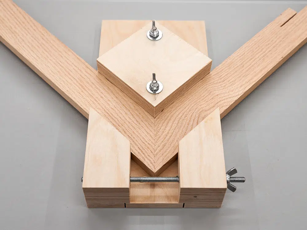
I cut the threaded rods to the right length and ground a flat spot on the end that gets glued into the handle:

The flat spot keys the rod in the handle and helps to keep it from turning after the glue sets.
Then used polyurethane construction adhesive to glue the studs in:

I assembled the wheels next using regular wood glue. I made sure that the blanks were lined up exactly before clamping:

I used a pin nailer to help hold the parts in alignment and keep them from sliding around while clamping. Another option is screws – drill pilot holes before gluing and then the screws will also act as clamps.
The upright assembly is three layers and that is glued and clamped up next:

After it was dry (the next day), I installed the t-nuts:

The wheels and the upper wheel bracket assembly after drying overnight:

Might be tempting to rush some parts, but I recommend giving these important assemblies a minimum of 8 hours to fully dry before removing the clamps. It can take that long for the glue that’s inside the joint to dry completely and reach adequate strength. If you want to speed this up, fast setting epoxy is the best option, or you can add screws permanently to hold the parts together.
While the glue was drying on the sub-assemblies, I mounted the pulley on the motor shaft and trued the face:

I have it held down to a piece of 2×8 using my homemade strap clamp and I set up a plywood tool rest for the 1/4″ chisel I used to do the work. This didn’t take much time and the video at the bottom of this page shows the process.
To fasten the lower wheel, I started by getting it very close with it held on the pulley with double sided tape. Again, the video blow shows this live and in person. After I had the wheel centered correctly, I drilled through to mark the screw hole locations on the pulley. I could then remove the wheel and finish drilling the holes:

Four screws hold the wheel on the pulley and I’ve found this to be the best, most reliable method for making this kind of connection. The pulley basically acts as a mounting flange for the lower wheel.
If the wheel is not perfectly centered (mine was close enough), you can true it in by turning off the excess, much like using a lathe. I did this in my previous belt sander project.
NOTE: The plans say to use 1-1/4″ screws to fasten the lower wheel, but it’s actually 1″ screws, as listed in the materials list.
Main assembly starts by fastening the upright assembly to the base, and here I’ve marked the exact location:

I used 5 minute epoxy to glue the upright to the base and let that set while I had lunch. With the epoxy dry, I could then drill and drive the screws from underneath, and not have to worry about it moving:

Take note of the orientation of the base during assembly. I marked “back’ on mine and that matches what’s in the plan.
I had to notch the rear motor bracket to clear the power switch:

My motor has this bearing cover on the back that sticks out, but if yours doesn’t, you’ll need to devise another way to support the back of the motor. One possibility is to drive screws directly into the back cover on the motor, as long as they are short enough not to hit anything. Best option is to use large hose clamps that wrap the body of the motor and hold it down to a plywood strip underneath. The strip can then be screwed to the divider at the front and the rear motor bracket at the back.
The sander is designed for the motor I have (which is very common) and you may have to make some adjustments to certain parts if using a different model. Keep that in mind as you work through this part of the assembly:

To stabilize the motor and keep it from turning, I glued two blocks between the divider and the front of the motor:

I later changed this to a better solution, but thought I show it here for the record. This build was a prototype and I worked through some of problems and challenges as I went along.
The platen is screwed to the divider and this has to line up with the front of the wheel and not touch it. Make adjustments as needed:

I made my platen from steel, but aluminum is also a good option. It can be made taller if needed.
The tracking bracket gets glued and screwed in place to the upright assembly:

This is another part that has a t-nut in the back and I installed that before fastening the bracket.
The front panel is fastened next and it a good time to talk about glue. The divider, rear motor bracket and front panel are all fastened without glue, since you may need to take the sander appart at some time for maintenance:

I also have the belt installed in this photo, to check the length and to look at the upper mount. Turned out there was a problem with my original concept for the “hardwareless” hinge for the upper wheel bracket, but I tried a few things and came up with an easy solution.
Speaking of problems, my original location for the tension adjust knob was slightly off:

I moved it and the plans have been updated.
The fix for the upper wheel bracket problem was to add two blocks at the top to build it out:

Again, this has been changed on the plans to correct the problem.
I made sheet metal rub plates for the tracking and tension knob contact locations on the upper wheel bracket assembly. I fastened these with double sided tape:

Another small problem in my original design was the screw locations on the right side of the lower wheel cover. The length of this part (and the disk table as well) needs to be adjusted after the main part of the sander is put together. Varying thicknesses of plywood can cause these parts to be too long, and they will need to be trimmed. I moved the screw locations farther in on the panel and you should cut the right side to adjust the length:

The disk table assembled after cutting it to the correct length:

The belt tilt table uses a butt hinge to operate, and that is fastened with 1/2″ wood screws. I didn’t have any, so the tips of my screws stuck through and I had to file them off flush:

Gluing on the strut attachment block… wrong – the bevel should face the other way:

In fact, it’s better to leave the block square and only plane the corner if needed. As it turned out on mine, the table went all the way down to 45 degrees without hitting:

The strut is fastened to the strut block with a single screw and washer. The screw is tightened, then slacked off slightly to allow the strut to operate:

With the upper wheel installed and the belt put on and tightened, I sanded a slight crown in the upper wheel using one of my sanding files:

I show this in the build video at the bottom of this page. The wheel doesn’t need much of a crown to help keep it tracking properly.
I also trued the front face of the lower wheel, since the sanding disk will be fastened to it:

The video shows this, as well. I later sprayed on several coats of polyurethane to create a better surface for the self adhesive disk.
This photo also shows the slight bevel on the inside of the lower disk cover. I did that to help improve dust collection from the disk.
Now on to the improved way to keep the motor stationary, first I cut out the blocks I glued in using my homemade dovetail saw:

I then screwed a piece of plywood between the motor and the divider, and drilled a hole partway into the nose of the motor:


A 2″ wood screw driven in locks the motor in place much better than the two blocks:

The plywood block is just fastened with two 1″ screws through the divider:

Not strictly necessary, but it does make the machine look cooler, I drilled the four holes in the upper wheel and chamfered the edges on my router table:

Also, when I reinstalled the upper wheel, I put some polyurethane construction adhesive on the end of the threaded rod before screwing on the outside nut. This will keep the nut from coming undone.
A better choice for the switch is the older toggle style, rather than this decora model. I made a plywood cover to make it more difficult to turn on the sander accidentally and epoxied that to the plastic plate:

I took the sander apart again and gave all of the parts two coats of polyurethane to keep it looking good and protect it from moisture. I let that dry for a full day before putting it back together again:


If you are interesting in building one of these for yourself, plans are available:

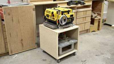
The plans includes the stand shown here.
I made a video showing the assembly of this sander: