


Making An Indexed Box Joint Jig Homemade Machines & Jigs
A newer version of this jig has been made with plans available. Read about it here.
To solve a problem, sometimes two heads are better than one. When it comes to designing a machine to do a simple task, it’s good to have the benefit of another viewpoint, someone who understands the challenges and can offer an alternate way of doing things. The fruit of a successful brain storming session may be a design concept that neither participant would come up with on their own.
I have such a brain storming session to thank for many of the features of this new jig. New and different ideas were discussed, examined, approved and rejected, with the result being several major changes that set it apart from other designs.
This is the prototype for this new jig:
It is a test bed, quickly made from cheaper materials to prove out the concept and test other ideas on. This was the project up until a few days ago, stalled for nearly two months – the stumbling block and the last piece of the puzzle was the advance mechanism. The advance mechanism is used to move the carriage (the carriage holds the parts that are being cut) to the right 1/4″ at a time.
As there is value to the collaborative approach, there is also value in a singular effort, where a tricky problem is worked at until it is solved. Such is the case here (as detailed in my blog entry “Trial & Error“) – I simply worked at it until I had a solution.
With this last hurdle cleared, it was time to build the final version. To do this, I started with some of the parts from the prototype, which would be the same on the final version.
One of the neat features of this jig is that it doesn’t ride in a mitre slot (I have no mitre slot on my table saw). Instead, it uses two 16″ drawer slides as linear bearings and this assembly gets clamped to the table saw’s regular fence. The advantage of this is that the jig is independent – it relies on the fence to locate it, and can be moved from one saw to another without making any changes. Once the jig is in position, the fence is locked down and it’s ready to use.
An improvement over the prototype, I’ve offset the drawer slides by 4”. This offset spreads the load over a longer distance, increasing accuracy by reducing lateral play.
The slides are fastened to the runners. The outer ones will be attached to the moving part of the jig. The centre runner will be screwed to the panel that is clamped to the table saw fence:
.jpg)
Just barely visible here, there is a very slight gap between the edge of the centre runner and the outer ones. This is enough for clearance. It could be wider, but that would potentially allow more settling dust to get in.
.jpg)
A piece of 3/4″ plywood is cut to size and screwed to the outer runners:
.jpg)
The panel that will clamp to the table saw’s fence is screwed to the centre runner. Glue is not used on any of these joints, in case disassembly is required for cleaning, lubrication or replacement of the slides.
.jpg)
Stop blocks are fastened to limit the free travel of the slides:
.jpg)
.jpg)
The slide assembly is now complete.
Moving on, the base is attached to the slide assembly. It is 1/2″ thick Baltic birch plywood and I use a trued framing square to ensure the base is perpendicular to the slide assembly:
.jpg)
Five screws hold it in place. No glue. As shown, the base is flush with the bottom of the panel that clamps to the saw’s fence. Both of these parts sit on the table saw’s surface, leaving no gaps underneath:
.jpg)
The jig is basically three major sub assemblies. The slider assembly, covered on the previous page; the rail and deck assembly and the carriage assembly.
The base is the first component of the rail and deck assembly. Attached to this is the sub-rail, made from two layers of 3/4″ Baltic birch plywood:
.jpg)
This is glued and screwed to the base, but not the slider.
.jpg)
Next is the main rail. This is made from straight, defect free hard maple and has several rabbets cut into it for other components:
.jpg)
The first of those other components is the deck. Like the base, this is also 1/2″ Baltic birch plywood, glued and screwed in place. The deck is actually installed before the main rail, with screws going into the sub-rail. Placement of these screws is very important, that none end up in the path of the blade that will cut through part of this assembly.
.jpg)
The next component to be installed is the track. This is screwed in place in a shallow rabbet in the main rail:
.jpg)
On to the carriage assembly, the front part of the carriage is recycled from the prototype. Already attached to it is the lower guide bar that fits into a 3/8″ x 3/8″ rabbet in the main rail. This guide bar helps to keep the carriage on the main rail:
.jpg)
With the front of the carriage in place, another piece is added to the rail and deck assembly. It’s a piece of solid maple, 3/4″ thick and flush with the face of the carriage. This supports the bottom of the stock clamped into the carriage for cutting.
Also, the end block is added to the carriage face. This is the start position for the cuts:
.jpg)
A new part is cut and screwed to the carriage assembly. It rides on top of the main rail. The one that was used in the prototype was too scarred from previous attempts to make an advance mechanism, so I just made a new part.
.jpg)
The locking blade is installed:
.jpg)
The locking blade is a piece of 1/8″ thick steel that pivots on a screw driven into the end of the wood. It swings down and fits in the slots in the track. The track / blade combination locks the carriage in position. Swinging the blade up allows the carriage to move.
.jpg)
The advance mechanism is fairly simple. The objective is to push the carriage to the right 1/4″ at a time. The first step was to make a rack that had evenly spaced saw teeth cut in. This is screwed to the carriage at the back, just above the deck. The lever assembly that makes up the rest of the advance is located on the deck:
.jpg)
The lever assembly is installed:
.jpg)
The lever assembly has a swing arm, a lever and two pivot points. The pivot point in the swing arm (“A”) lets the lever swing forward and engage a tooth in the rack. The bolt near the middle of the arm (“C”) limits the arc and is in a slot in the arm. The pivot point on the right (“B”) lets the lever swing side to side. By engaging the lever in the rack and pushing it to the left, the carriage moves to the right. The round stop controls how far the lever will push the carriage and is adjustable by rotating it, as the centre mounting bolt is offset. Once the lever is released, the tension spring returns it to its starting position.
One lever click moves the carriage exactly 1/4″ at a time. To cut 1/8″ box joints, the carriage moves one click, or 1/4″, To cut 1/4″ box joints, the carriage moves two clicks, or 1/2″ and so on. Three clicks for 3/8″ joints, four clicks for 1/2″ joints. Simple and easy to keep track of, the jig is designed to use a dado blade, to create joints of standard size.
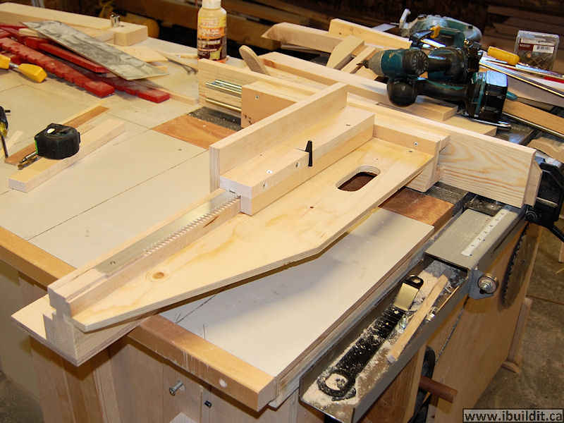
A handle cutout is made close to the lever assembly. This is to push the jig forward into the cut and pull it back out of the cut. Having it close to the lever makes it convenient to use my thumb to toggle the lever:
.jpg)
Some test cuts. 1/8″, 1/4″ and 3/8″ box joints, in materials of various thickness. The jig is capable of cutting panels up to 26″ wide, as shown in the sample at the bottom of the picture.
.jpg)
The completed jig:
.jpg)
I made a video of the jig in action, cutting 3/8″ joints in 3/4″ pine:

Here’s one of it cutting a box joint that is 26″ long:
This version of my box joint jig is the precursor to my new Advanced Box Joint Jig and my Ultimate Box Joint Jig. Although you can build this one, I recommend those, since there are plans available and those jigs are easier to build.


