Rotary Tool Drill Press Homemade Machines & Jigs
This is a project that I’ve wanted to do for some time: a drill press for my Dremel rotary tool:

I made a fairly basic drawing with SketchUp, to work out the overall design and some of the dimensions. I went back and forth from the drawing to a full sized mock up, to sort out the details and made changes as I went. For something like this, a mock up is the way to go, since it lets you get the feel of things in the physical world that you don’t get from CAD. For instance, how the quill works when you lever the handle, or how the head slides up and down on the column. Since this is a relatively small project, the time spent and material used in building the mock up was fairly insignificant when I factor in how much easier it was to build the actual press.
Here’s a video showing the press, with a short demonstration of it in action:

To get started, I cut out some parts:
Two pieces of 1/4″ plywood, one piece 3/4″. This make up the clamp that holds the rotary tool.
.jpg)
.jpg)
These parts are glued and pinned together, then clamped for thirty minutes, to let the glue set. I’m relying on the strength of the glue for much of the this project, as it is not subject to any serious stresses. Having a pin nailer makes glue assembly go much faster and accurately since it stops the joint from slipping while it’s clamped.
1/4″ holes are marked and drilled for a carriage bolt that will be installed later.
.jpg)
This is the ‘quill’ (calling it that for want of a better term) and it moves up and down on dovetail ways. The half-dovetail sections that are on the quill are fixed, while the full-dovetail that is attached to the head is adjustable. This gives the ability to take up slack that may come about from wear, or wood shrinkage. I’ll go into more detail on that a bit later.
The quill half-dovetail sections are made from solid hardwood and are glued, pinned and clamped
in place, one at a time:
.jpg)
.jpg)
The excess wood is cut off of the sides of the dovetails, to make them flush:
.jpg)
.jpg)
It’s a good fit. The parts were sized to work with this particular model (Dremel 400).
A hole is drilled at the back of the quill to access the upper screw in the dovetail, so that it can be adjusted after the unit is assembled. The dovetail is then loosely screwed to the head using fine thread drywall screws – fine thread drywall screws are sold for use with metal framing, as opposed to wood screws, which have a courser thread.
.jpg)
.jpg)
Here’s how the dovetail fits:
.jpg)
Notice the space at the narrow part of the dovetail. The dovetail can be screwed in tighter, to take up slack as it it wears. These parts are lubricated with petroleum jelly for smooth action. I find this better on raw wood than paraffin wax, as it doesn’t have the initial ‘stick’ before it moves.
The column clamp is made up, in the same way as the quill clamp, and is attached to the make up the head.
.jpg)
.jpg)
This completes the bulk of the assembly of the head / quill. I re-thought this several times until I worked the design down to this simple structure. This is a good example of a new way of doing things for me, where I will come up with a design and immediately tear it apart and study it to figure out better, more simple ways to get it done. My original concept for this assembly was a lot more complex than this.
The base is yet another piece of my cabinet door cutout and the column is some clear spruce – 1-1/2″ x 2″ x 14″ tall. The base is screwed to the column with four 3″ long wood screws:
.jpg)
.jpg)
The screws are angled inward slightly, toward the centre of the column – this allows me to spread them out a bit further, to add strength and reduce the chance of splitting the wood. There wasn’t any glue used, as it probably wouldn’t add much strength to the joint.
The head assembly fitted on the column:
.jpg)
There is a 3/4″ sealed bearing at the back that hold the head tightly on the column, but lets it slide up and down easily:
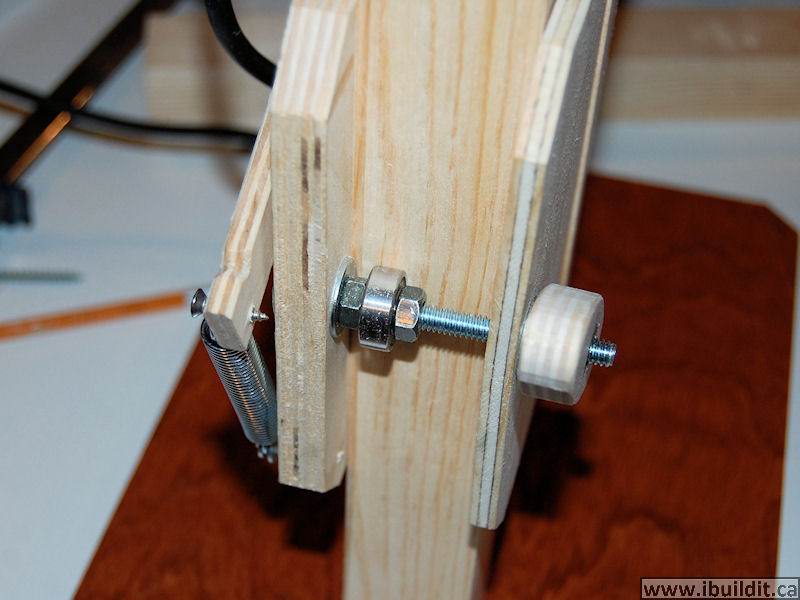
.jpg)
I made a couple of knobs from plywood. Simple enough, just a 1/2″ hole, part of the way through and a 1/4-20 nut glued in.
The arm attached:
.jpg)
The fixed pivot is on the head. A slot is cut in the arm at the quill for the travel in the arc as the arm swings up and down.
Red arrow points to the stop that limits how far down the quill can travel:
I limited the range of motion to 1-1/2″, figuring this would be plenty for this small press.
.jpg)
.jpg)
The other stop limits how far up the quill can go. I initially used rubber bands to load the arm, but later located a suitable spring at the hardware store.
The ‘glamour’ shots:
.jpg)
.jpg)
.jpg)
The base has a layer of the same rubbery material that I glued onto the bottom of my Belt Sander Platform to keep it from moving around.
I made a three part video series covering much of the build process.
A fun project and really handy as well. It will be a permanent fixture in my electronics lab.