


Making The Advanced Box Joint Jig Homemade Machines & Jigs
Not long after I finished the previous version box joint jig, I came up with several changes that could be done to improve the design. I also recognized that having it open ended, and able to cut stock twice as wide as it’s one-pass capacity, I could make a much smaller version that would be easier to build and more compact to store.
Since most of the joints I cut are in stock that is 6″ wide or less, this seems like a more practical design. If I want to cut box joints into a panel wider than 7″, this jig can do it – joints up to 7″ wide in a single pass and 14″ wide in two passes.
To start off, here is a video I did showing the assembly of the jig from start to finish:

And here is how to setup the jig to use and some sample cuts:
The bulk of the jig is made with plywood. The advantages of using plywood are many, with very few disadvantages. Good plywood is flat, consistent thickness and dimensionally stable. It doesn’t warp or twist under normal circumstances. The biggest plus for a jig like this is that it doesn’t move like solid wood will, it’s pretty much impervious to seasonal expansion / contraction. This means that the jig should work as well in the summer as the winter.
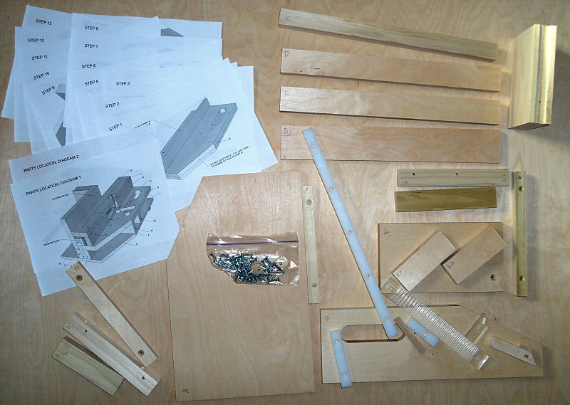
Before getting started, I took the time to print the plans and put them in a ring binder. This keeps them organized and together in one place:
.jpg)
I then took the time to cut each of the parts as detailed in the plans. Shown here is everything needed to fully assemble the jig. All of the screw hole locations were laid out, drilled and countersink for the #8 wood screws. I use a 1/8″ brad point bit to drill the holes, then countersink separately. I find this gives better results than a one piece drill / countersink bit:
.jpg)
Step one in the assembly is to glue and clamp part B to the bottom, part A. This is probably the most important step, and extra care should be taken to ensure that part B is exactly right. Every other step after this depends upon this one being correct. To help, part F is used as a clamping guide, but be careful that it doesn’t get accidentally glued in place:
.jpg)
After the glue on part B has had some time to dry, the next step is to glue and clamp part C in place.
.jpg)
And glue and screw part P to the front of the jig:
.jpg)
Step 3 is to glue and clamp parts D, E1 and E2 in place. Set aside to let the glue dry for a few minutes:
.jpg)
Next, glue on the deck, part F:
.jpg)
It’s important that the top of part F be flush with the top of part B, and if not, adjustments should be made at this time to correct this. When the glue has set on part F, part R is screwed in place. Part R is the main guide bearing, and I’m using UHMW plastic for that, but any hardwood would also work well, especially if it is saturated with oil. A naturally oily wood could be used as well.
Step 5 is a quick, easy one: screwing the advance lever and cams in place. The advance lever needs to move freely, so driving the screw in snug, then backing off a bit should allow it to operate smoothly:
.jpg)
Glue and screw parts L and M together. These make up the stock holding carriage:
.jpg)
A dado is cut in part M for another piece of UHMW plastic that acts as the front guide bearing. This will need to be adjusted to put it in contact with the bottom and the front guide rail, part P:
.jpg)
The carriage assembly is put in the jig and shimmed up about 1/32″ using folded over paper:
.jpg)
Then part N is marked and screwed onto the back of part L. It is recommended that part N not be glued, since it may have to be adjusted later:
.jpg)
In step 8, part N is removed temporarily to attach the upper guide bearing, part X. This can be done with part N in place, but drilling the pilot holes for the screws may be tricky.
Part O is fastened to part N with screws (no glue) and may need to be shimmed to fit on part R properly. If there is too much play, part N may need to be planed to take up the slack:
.jpg)
Step 9 is to attach parts G and H to the deck, part F. These are glued and screwed in place. Part V is glued and clamped to part G, and the clamp should stay on for several hours to ensure that the glue has fully set. Although it might seem wimpy, the wooden spring is actually quite robust and should give years of service without any problem. Of course, if it did break, it wouldn’t be difficult to make a replacement:
.jpg)
Moving on to assembly step 10, the locking blade is attached to part I with a flathead wood screw. Part I is then glued and screwed to part K, then part I is glued and screwed to part G. The carriage needs to be in place for this step, since part K fits up tight to it:
.jpg)
In step 11 the division plate is located and fastened. With the carriage in the start position, slide the plate in and swing the locking blade down to lock into the first notch. Then make a mark at the open end to show where the plate will go. Unlock the locking blade, slide the carriage out, and attach the division plate to part O:
.jpg)
.jpg)
Next, attach part J to part K and part H. This piece is just screwed in place, no glue. It may be necessary to remove this at a later date to replace a damaged or worn locking blade, so it needs to be held in with screws only. It should butt up tight to the locking blade to give it extra support:
.jpg)
The basic assembly of the jig is now complete.
Cutting the division plate
UPDATE: There is an improved way to cut the division plate. Details here in this article.
The most accurate way to make the division plate is to use the simple jig shown in this video. Use a thin kerf circular saw blade (7-1/4″ is best) on your table saw and cut the plate. Here I’m using a 1/4″ hex driver bit as the spacer:
.jpg)
.jpg)
It’s a good idea to cut the plate a little longer than needed, the trim to the right length on the ends.
The first notch on the right side of the plate should be 7/8″ from the end:
.jpg)
Cutting the locking blade
The locking blade is a small part that needs to be made fairly accurately, and I came up with a way to cut it reasonably safely with the table saw. I’m cutting it from a larger piece of wood, one that can be firmly held.
The point on the locking blade is about 53 degrees, so to cut that, I tip the blade to 64 degrees and make the first cut 1/8″ in from the edge. The blade is only sticking up about 1/4″. For the next cut, the block is turned around and the fence moved over. The blade is at the same height and angle:
.jpg)
.jpg)
Next is a 90 degree cut, nearly 1″ deep:
.jpg)
Then a shorter 90 degree cut frees the part:
.jpg)
.jpg)
The piece is then cut to length and shape:
.jpg)
The pivot hole and countersink are marked and drilled. The locking blade is now finished.
.jpg)
Another way to form the point on the locking blade is to carefully sand it to shape from a strip of wood 1/4″ thick and 1″ wide. This is the method I used for the prototype. The point does not have to be precisely located on the locking blade, since the jig relies on setting the division plate in the right place. It should just fit in the notches in the plate without bottoming out in the notch.
Some pictures of the completed jig:
.jpg)
.jpg)
.jpg)
And a look at two joints, a 1/8″ and a 1/4″ cut in spruce:
.jpg)
Plans are available for this project here:
Advanced Box Joint Jig

A ready to assemble kit is also available for this jig:
Additional Info
Over the time this jig has been available, many people have built it or have asked me some specific questions about using it. I figure the best way to answer those questions is to write this addendum to the build article. This should help those that have either built a jig already, or are considering getting the plans.
Here’s a video showing how to use the jig on the router table:
Here is a video I made going through some of these questions and showing how to cut box joints on this jig with a single saw blade:
Whenever I use the jig, I clamp a stop block in the miter slot to keep the jig from going too far forward:
.jpg)
It only has to go far enough ahead for the blade to cut through the stock, and that’s where the centre line of the blade meets the face of the fence.
I’ve often been asked where to get a blade that is 0.06″ thick, as specified in the plans for cutting the division plate. Most thin kerf 7-1/4″ skilsaw blades are about this thick and are cheap and readily available:
.jpg)
The actual thickness of the blade is not really important, just that you have enough material on both sides of the cuts to be strong enough, and that the locking blade slots into it without bottoming out.
.jpg)
Many people have contacted me to ask if the jig can be used with just a regular saw blade, and not a dado set. In the “Setup And Use” video (first page of this article), I demonstrate how to cut 1/8″ box joints using two thin kerf blades stacked in my saw. At the time, the saw I was using had some runout on the arbor (side to side wobble on the blade), and using those two blades that totaled less than 1/8″ in thickness made a well fitting joint. On my newer saw, I have a lot less runout and I can use a standard 1/8″ thick blade to make 1/8″ box joints:
.jpg)
.jpg)
It occurred to me that the jig could cut wider joints if you move the stock away from the side fence by the right amount after the first series of cuts is made. This method is difficult to describe, but is very clearly shown in the video above.
As mentioned, it will take some experimentation to figure out the spacing, but once you know it you can use it over and over again. I used a drill bit as the spacer, just to save time and simplify the video, but you could carefully cut a hardwood shim the right size. You could also make a shim from layers of thin sheet metal or plastic (pop bottles).
In the video, I cut a 1/4″ box joint, but the same method can be used for larger ones. Still, if your saw will take a dado blade set, that would be the best choice for wider joints.
.jpg)
Although I mentioned it before in a few different places, it bears repeating here that when using the jig with a dado stack, the shims that come with the dado set are used to fine tune the joint. The jig itself is set to move exactly 1/4″ at a time, and does not have any “fine tuning” built in to complicate the build, break or loose accuracy. The way to ensure perfect fitting box joints is to take the time to make the division plate as precisely as you can. The method shown in this video is the best way to do that:
The video shows the older version of the division plate being cut, but the same method works just as well for the newer version.
The jig I used for the video at the top of this page was an old one (I had done some failed experiments on the newer one, and it’s currently out of commision…) and the wooden division plate was cut by moving the table saw fence over 1/4″ at a time, and I still got really well fitting joints:
.jpg)
.jpg)
It’s important to keep in mind that there should be some looseness to the freshly cut joint, to allow for glue. Any small gaps can be filled with fine sawdust mixed with glue before the glue sets, or with wood filler after.
The last thing to talk about is how to use the jig with a dado set on a left tilting arbor saw (the dado stacks over to to the right, the arbor nut is on the right side of the blade).
As mentioned in the “setup and use” video, you should setup the jig initially for a 1/4″ dado (if you saw is capable, if not set it up for an 1/8″ blade). As shown below, the 1/4″ dado would line up with the face of the side fence:

To cut a 3/8″ joint, you will have to move the carriage over 1/2″ to begin. This will leave a 3/8″ space between the dado blade and the side fence, which will be the first finger. As you add to the thickness of the dado blade, it will cut into the right side (when standing behind it) of the base, as shown in the picture below:

For a 1/2″ joint, the carriage would move over 1/4″ and the dado would be in line with the side fence:

For a 5/8″ joint, move the carriage over 1″, leaving a 5/8″ space between the blade and the side fence:

For a 3/4″ joint, move the carriage 1/2″:
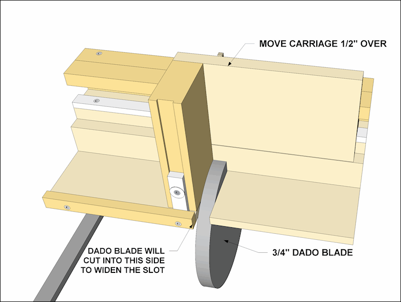
And so on. There is no loss of capacity and you will not have to cut into the side fence. All of the illustrations above shoe the starting position for the carriage.


